Local Law Important Dates Reminder

Local Law Important Dates Reminder

September 28, 2022    Newsroom

As 2022 is drawing to a close, we would like to remind you of upcoming key dates regarding compliance with energy Local Laws:

October 1, 2022: This year’s NYC Building Energy Efficiency Rating label becomes available

How to download the letter grade:

    1. Go to the DOB: Safety website.
    2. Scroll down to Get your Building Energy Efficiency Rating. 
    3. Enter your building’s Borough, Block Number, and Lot Number.
    4. If your letter grade is N, you’re done! Buildings with an N grade are not required to display their letter grade. Otherwise, you have to download and post it by…

October 31, 2022: The deadline to download and post the letter grade

How to post the letter grade:

    1. Print enough copies of the letter grade to post it at every entrance. The printed copies should be 8.5″ x 11″ and can be color or grayscale.
    2. Post the letter grades conspicuously near each entrance. It should be visible to the public and not obscured by other papers.

December 31, 2022: Prepare for energy benchmarking in the start of 2023

Energy Benchmarking Tips:

    1. Collect your electric, natural gas, fuel oil, and water bills spanning 1/1/22–12/31/22.
    2. Request these bills from any commercial tenants you may have as well.
    3. 2023 will be the last year before Local Law 97 comes into effect.
      • Pay close attention to any increase in energy consumption and plan any last-minute changed needed to stay under your carbon emissions limit.
      • Take care in organizing and retaining your utility bills–they are the sole proof of your actual energy consumption and will be needed for reference if your building is fined for excess carbon emissions.

Our team will continue to follow up regarding benchmarking, but please feel free to reach out in the meantime with any questions!

Energy Auditing

Energy Auditing

February 2, 2022    Newsroom

A building energy audit is a process of determining how a facility uses energy, the types of energy used, the energy cost, and identifying opportunities to reduce consumption without decreasing occupants’ thermal comfort or life safety.  New York City (NYC) Local Law 87 (Energy Audits and Retro-Commissioning) mandates periodic energy audits for buildings that exceed 50,000 square feet.  The New York State Energy Research & Development Authority (NYSERDA) and local utility companies require an energy audit as a requirement for participation in some of their utility incentive programs.  And NYC Local Law 97 (Carbon Emission Limits), scheduled to be implemented in 2024, will require some level of energy auditing to determine a property owner’s actual carbon emission and potential financial penalties.

Types of Building Energy Audits

An energy audit is often also referred to as an energy assessment, survey, evaluation, or investigation. There are four commonly accepted types:

  • Level-0 (Benchmarking Audit or ASHRAE Preliminary Energy-Use Analysis):

This audit is an analysis of energy use and cost to determine a benchmark index such as Btu (British Thermal Unit) per square foot per year. It involves analyzing annual utility bills and is relatively quick for simple building layouts. NYC Local Law 84 (Energy Benchmarking) requires annual benchmarking submissions for buildings exceeding 10,000 sq. ft.

  • Level-1 (Walk-Through or ASHRAE Level-1):

This audit involves a cursory Level-0 analysis and quick identification of recommended energy improvement measures that are no-cost or low-cost. On-site surveying is limited to a few hours with a small team of auditors, and the survey cost is small. Estimated energy savings and implementation costs are rough estimates. A Level-1 audit is ideal to determine if a building has potential energy reduction and cost savings. If a building does not, the auditing effort is ended with no further resources expanded. If a building has potential, a higher auditing effort is necessary to quantify that potential.

  • Level-2 (Energy Survey and Analysis or ASHRAE Level-2):

This audit involves a more detailed utility data analysis and surveying of building conditions and energy consuming equipment. The surveying effort depends on the size and complexity of the facility, and it may last multiple days or weeks with a large team or multiple teams of auditors. This effort is also dependent on the complexity of recommended energy measures. Auditors can perform more detailed energy calculations, take on-site measurements, and collaborate with contractors and specialized consultants to provide more realistic savings and implementation costs. Building owners can use the results to plan their energy projects and use the report to comply with NYC Local Law 87 requirements.

  • Level-3 (Detailed Analysis of Capital-Intensive Modifications or ASHRAE Level-3):

This audit expands upon the Level-2 effort. Typically, building owners will decide which recommended energy measures they wish to pursue from the Level-2 audit. Auditors will refine engineering and economic analysis, backed by detailed field data collection, and develop a preliminary scope-of-work or design. Implementation costs result from actual contractor bids. As a result, these audits are also referred to as investment grade audits or IGAs.

Energy Auditor Qualifications

An energy audit team will typically consist of personnel with different engineering and energy-related expertise. The team composition may vary with the audit level and energy measures being analyzed. Regardless of efforts, energy auditors or team leaders should be certified energy audit professionals. NYC Local Law 87 requires an energy audit to be conducted or supervised by personnel with one of the following certifications:

  • Certified Energy Manager (CEM) or Certified Energy Auditor (CEA)
  • High Performance Building Design Professional (HPBD)
  • Building Energy Assessment Professional (BEAP)
  • Multifamily Building Analyst (MFBA) – audits of multifamily residential buildings only

Energy Audit Results

The results of an energy audit should help building owners understand how they are using energy, how their energy consuming equipment contribute to energy use, the cost of energy use, and ways to reduce that energy use. The audit could also produce recommendations for operations and maintenance improvements. At a minimum, NYC Local Law 87 requires a Level-2 audit to provide:

  • Reasonable recommendations to reduce energy use and/or building operation cost
  • Annual energy savings, implementation costs, and simple financial payback
  • Benchmarking results
  • A breakdown of energy use by system and predicted energy savings by system
  • A general assessment of how the major energy consuming equipment and systems impact energy consumption

Water Conservation

Although an energy audit investigates the use of electrical and fossil fuel energy in heating and cooling systems, it will often include a survey of domestic water use within a building. At a minimum, water must be conditioned or pumped to the point-of-use. Reducing water consumption can result in significant cost savings due to high use and water and sewer costs.

Building Owner and Stakeholder Involvement

A successful energy audit is a team effort consisting of the audit team, building owner, operators, and other stakeholders such as tenants. Building owners should convey their expectations of the audits, and provide guidance on their priorities, constraints, and other factors that could help focus auditing efforts or influence energy measure considerations. This helps reduce auditing cost and optimize efforts.

Do I Need an Audit?

Collado Engineering can help you determine what type of audit is right for you and/or what you need to comply with New York City requirements. Our certified energy professionals can provide detailed analysis and recommend realistic energy conservation measures.

WHAT YOU SHOULD KNOW ABOUT FIRESTOPPING

WHAT YOU SHOULD KNOW ABOUT FIRESTOPPING

March 22, 2021    Newsroom

While firestopping and firestopping inspections have been required for a long time, they are not always given the attention they deserve. The A/E industry has developed a false sense of comfort in simply seeing the red goop (intumescent fire sealant). It is not that the industry does not think fire stopping is important, the issue is that there is a lack of understanding of the basic requirements. Currently, there is a renewed effort by municipalities to ensure that firestopping and firestopping inspections are performed properly.

Let us look at what firestopping is, and why we should all be paying more attention to it.

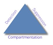
Compartmentation is a passive fire protection system designed to impede the spread of fire and smoke. It is a key component of the life safety triangle and has been a Code requirement for many years. Firestopping is an enhancement of that system, it is used to seal around openings and between joints in a fire-resistance-rated wall or floor assembly; ensuring the fire rating of a compartment is achieved or maintained. Compartmentation, and the required separation of adjacent spaces, is the purview of the architect, as is the construction of the barriers to achieve the necessary separation and the sealing of joints between these barriers.

However, penetrations through the fire rated barrier are usually required to accommodate the passing of building system components, which is typically the responsibility of the MEP engineer, and the focus of this article.

It should be noted that the “time” fire rating criteria commonly used, is only one of several criteria that must be defined to properly treat the penetrations.

F-Rating: The amount of time, in hours, before a fire spreads from the fire side to the non-fire side of a fire-rated assembly (e.g., by burning through each successive layer of materials).

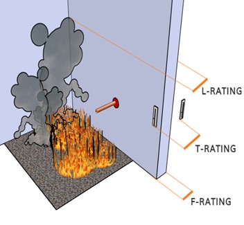
T-Rating: The amount of time, in hours, before the temperature of the non-fire side of the fire-rated assembly or penetrating item reaches 325°F. Even if the fire barrier prevents the passage of flames during a fire, it is possible for the surface temperature of the non-fire side to become high enough that flammable items (e.g., lampshades, paper, fabrics, etc.) may spontaneously combust.

L-Rating: The amount of air, in CFM/ft2, that leaks through a joint or penetration firestopping system at ambient temperature and at 400°F.

W-Rating: The watertightness of a firestopping system measured against 3 feet of standing water for 72 hours. The intent of the W-Rating is to gauge the extent to which a fire barrier installed in floors will deteriorate when exposed to moisture.

Other: Mold and mildew resistance and seismic performance may also need to be considered based on the specific use case.

The selection of firestopping caulk is unlike other items design professionals specify. By now most design professionals have caught-on that firestopping should be a system, and their documents call for the use of firestopping systems, and some, even call for a UL-listed system to be used. What is often not understood, is that the system is made up of the penetrating item (copper pipe, EMT conduit, etc.), penetration size, the barrier material being penetrated, the annular space between the penetrant and the barrier, and even how the penetrant passes through the barrier. Add to that the required performance criteria and you have the system. Now, find a caulk that has been tested under those conditions, and all that is left to do is ensuring that it is installed in accordance with the way it was tested and listed. Not so easy, right?

Firestopping systems must be tested and approved for use by a Nationally Recognized Testing Laboratory (NRTL). NRTLs, such as UL, list systems for the specific conditions under which they were tested. If the same caulk material, penetrant, and barrier material were not tested in a specific arrangement, it would not carry a listing for that arrangement. While there are thousands of listed firestopping systems from many manufacturers that cover most common configurations, installation conditions and rating requirements, there may be instances when the installation does not match the listing exactly, and an Engineering Judgement (EJ) may be required from the fire caulk manufacturer. An EJ is a written document, usually in the form of a letter or report, stating that a given firestopping installation is likely to be effective in preventing the spread of fire and smoke even if it was not actually tested in that specific arrangement. EJs should only be used as a last resort; if a project requires more than a couple of EJs, it may be a sign that not enough effort was spent in selecting the firestopping systems.

Since the selection of firestopping systems requires knowledge of how the penetrants are installed through the rated partitions, it is impossible to specify firestopping systems on the design documents. Design professionals should provide a performance specification and enough details for the contractor to be able to select an appropriate system during the construction. For example, the L, T, F, and W-Ratings should be clearly identified, as well as details of the special inspection requirements.

So, what about those inspections?

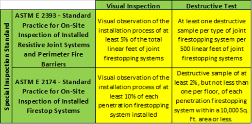
The International Building Code has included new firestopping inspection standards, since the 2012 codes were adopted. These standards were put in place to help increase the efficiency of firestopping systems and inspections. The ASTM firestopping inspection standards have also been adopted into the 2014 NYC codes. The two relevant ASTM Standards are E-2174 (Penetrations) and E-2393 (Joints); among other things, they require the firestop inspector to be completely independent of and divested from the installer, contractor, manufacturer, or supplier.

Special inspections require either visual inspection or destructive testing of each firestopping system installed on a project. Ten days prior to the installation of the firestopping materials, the contractor is responsible for providing the special inspector the installation schedule, NRTL listings for each unique firestopping system being used on the project, and any other material the inspector may require. Visual inspection requires that the inspector witness the installation of a percentage of each firestopping systems being used to ensure they are installed per the listing criteria. Destructive testing requires the contractor to cut into a small percentage of installed firestopping systems to determine if they were installed in accordance with the listing criteria. Destructive testing is the only option when the installation has not been coordinated with the special inspector and might also be used if the inspector cannot spend all that time in the field. It is important to note that the contractor will be responsible for completely removing and reinstalling the firestopping systems that have been destructively tested once the inspection is completed. To avoid costly change orders during construction, the design professionals should make the contractor aware, via the design documents, that destructive testing may occur. Table 1 details these requirements.

Effective fire stopping is essential to ensure the passive fire protection systems of the building perform as expected. All involved must have a deep understanding of the requirements and each other’s role in the process.

BY: Alec Raia, Danielle Koch, Daniel Lennon


New York State Clean Heat

New York State Clean Heat

February 25, 2021    Newsroom

Electrification may be the latest industry buzzword, but government agencies in New York have only increased the number of incentives programs which aim to reduce the state’s dependence on fossil fuels. If you have established electrification as part of your portfolio-wide energy strategy, consider using the funds the state has reserved to help you achieve your goals.

One of the state’s programs, NYS Clean Heat, promises funding for the most popular alternatives to oil- and gas-fired equipment: air-source heat pumps (which includes VRF) and geothermal (ground-source) heat pumps.

Eligibility Requirements
1. For Existing Buildings:
An active electric utility account.
2. For New Construction:
Design Phase – Intent to obtain a temporary utility account
Construction Phase – Temporary utility account
3. The site must be/will be occupied year-round
4. Installed heat pumps must be used for heating in order to offset existing fossil fuels (e.g. natural gas, oil, steam)
5. Heat pumps must be designed to provide domestic/service hot water heating and/or both space heating and cooling. Heat pumps used primarily for space cooling are not eligible.

Incentive Amounts
The incentives available vary by electric utility and are based on the size of the systems installed (per 10,000 Btu/h):

How to Apply
Only Participating Contractors approved by NYSERDA and your electric utility can apply for these incentives. As an approved Participating Contractor for the utilities above, COLLADO ENGINEERING can:

– design systems which meet the program requirements
– coordinate with an approved installing contractor
– perform pre- and post-installation inspections
– submit the required energy savings calculations
– interface with program representatives on your behalf

If you have been thinking about upgrading existing equipment or are developing a new building, COLLADO ENGINEERING can assist you in developing designs that take advantage of these incentive offers and pursue these opportunities with your local utilities.


Collado Earns Top Engineering Excellence Award for Haven Plaza Resiliency Project

Collado Earns Top Engineering Excellence Award for Haven Plaza Resiliency Project

February 25, 2021    Newsroom

Collado Engineering has earned a 2021 Diamond Engineering Excellence Award in the category of Building/Technology Systems for its innovative design of a flood resistant Utility Services Building for Haven Plaza, a mid- to low-income housing complex on Manhattan’s Lower East Side. The plant is part of a resiliency program to harden infrastructure for the complex, which was massively damaged in 2012 by Superstorm Sandy.

Presented by the American Council of Engineering Companies (ACEC) New York affiliate, the Engineering Excellence Awards (EEA) are judged on a rigorous set of criteria, which includes complexity, innovation, and value to society. Diamond award winners from each state chapter can compete for ACEC’s prestigious Grand Conceptor award in February 2021.

“We are so pleased to be honored with the highest award in the Building Technology/Systems category for the Haven Plaza project. Our work has had an immediate and direct impact on average New Yorkers, providing them with the security that their lives would not be disrupted by another flooding event like Sandy,” said Andy Hlushko, President of Collado Engineering.

Financial support for the project was provided by the New York City Department of Housing Preservation & Development (HPD) and the New York City Housing Development Corporation (HDC) under the City’s Build it Back program.

Moving to Higher Ground, Greater Self-Sufficiency
In the wake of Sandy’s surge, the residents of all 371 apartments in the four buildings that comprise Haven Plaza were stranded without power, heat and hot water service and only partial cold-water service, due to flooding of critical mechanical and electrical infrastructure equipment located in the cellar of two Haven Plaza buildings. An explosion and subsequent power outage at the adjacent Con Edison power plant knocked out electrical service to the remaining two buildings of the complex.

Haven Plaza Square LLC, an affiliate of the Association of New York Catholic Homes and the New York Institute for Human Development, commissioned Collado Engineering, CTA Architects and Robert Silman to design an infrastructure system that would withstand the effects of a future natural disaster, allow the complex to be self-sufficient, and reduce operating costs.

Collado’s solution—a new free-standing Utility Services Building with a first floor that stands one foot above the FEMA base flood elevation and six feet above ground level—houses a new on-site dual fuel steam boiler plant, the domestic hot water generation equipment, and electrical service provisions for the plant and 4 Haven Plaza. The boilers, which normally operate on gas, can be switched to diesel fuel, if necessary, via a diesel fuel storage tank located in a floodproof “bathtub” cellar area. Electrical infrastructure for 1, 2, and 3 Haven Plaza was also raised to elevated platforms for floodproofing. Each building is equipped with manual transfer switches, allowing portable generators to provide standby power to critical loads.

Public Investment on Display
CTA Architects designed the utility building with transparency in mind, utilizing 1,300 sf of glazed curtainwall, 1,500 sf of metal façade and 500 sf of green wall. Prominently visible in the busy East Village neighborhood, the plant showcases for the public the investment made in the property’s engineering infrastructure.

The building’s poured concrete structure, designed by Robert Silman structural engineers, allows for a column-free space to accommodate the large equipment. Due to the low-bearing quality of the soil, fifteen 100-ton capacity concrete piles were incorporated into the foundation system. Location of the new Utility Services building was strategic, enabling the use of much of the existing underground distribution on site.

All work was completed while the housing complex remained occupied, requiring continuous communication with residents to coordinate service shutdowns and schedule.

HVAC Air Treatment with COVID-19

HVAC Air Treatment with COVID-19

July 9, 2020    Newsroom

With the tri-state area reopening amidst the ongoing COVID-19 pandemic, many building owners and operators are looking for ways to mitigate the spread of the virus to building occupants. In addition to disinfection of commonly touched surfaces, social distancing, and screening procedures, the building’s HVAC system – the respiratory system of the building – has come under scrutiny as a potential mechanism for circulating contaminants throughout the building. Vapor droplets suspended in the air are the primary carriers of viruses, so their removal is key to slowing the spread of infection. While no one approach offers a silver bullet for stopping the spread of airborne particles, each will reduce the likelihood of transmission.

What Options Do I Have?
The American Society of Heating, Refrigeration and Air Conditioning Engineers (ASHRAE) sets the standards for indoor air quality. While ASHRAE’s list of recommendations for air treatment options pertain mostly to healthcare facilities with high risk of disease transmission, these approaches can be implemented by any building.

Filtration: Removing contaminants from the airstream to prevent them from recirculating throughout the system.
Dilution: Increasing the amount of outside (ventilation) air to reduce concentrations of contaminants.
Elimination: Deactivating or destroying living biological contagions in the air stream.
Environment: Maintaining the proper indoor ambient air conditions that are unfavorable for contagions.

Many of our clients are asking the question: What options do I go with? The answer is: It depends. Existing systems need to be evaluated to confirm that they are operating as designed and after any existing issues have been addressed, strategies for mitigating infectious spread can reviewed and implemented. Understanding the implications of the options below will illuminate an optimal approach within the constraints of the building’s HVAC system.

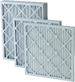
Filtration: Most existing HVAC systems already have filters installed, so ensuring that these are being changed regularly and properly is important. Upgrading filters to higher MERV or HEPA levels with higher entrapment efficiencies for smaller particles can improve contaminant removal. However, it is important to understand the performance capabilities of the system before installing. Adding higher rated filters increases pressure drop through the system, which can result in poor airflow and may require modifications to the filter racks or fan operating parameters. Bi-polar ionization can be used to enhance filtration by generating ions that attach to contaminants, making them larger and more susceptible to filter capture, thus allowing for the use of lower filter ratings and avoiding airflow issues. Stand-alone filtration or ionizing units are effective for elevators.

Dilution: Buildings are required to provide ventilation air to occupied spaces, typically by mechanical means. By increasing the amount of outside or ventilation air to each system, the air in the zone is displaced and concentrations of contagions reduced. Ventilation air rates should be increased as much as possible, even to 100% if outdoor and indoor conditions allow. However, too much outside air could burden the system’s fixed heating or cooling capacity and result in uncomfortable space temperatures or worse, creating humidity levels that promote infection transmission. The proper balance of timing and duration of increased ventilation rates need to be carefully programmed into the system’s operation.

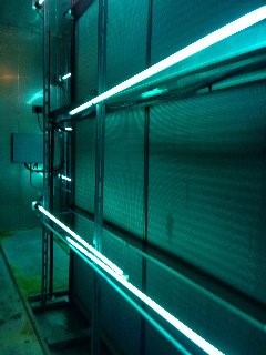
Elimination: UV-C light is effective at inactivating many different pathogens such that they cannot replicate. While this approach is highly effective in static operations such as air coil sterilization and surface disinfection, there is a misconception that it will effectively deactivate viruses in a moving air stream. In most applications, the necessary modifications to provide the proper dosage to moving air in a single pass to deactivate all the entrained virus would be extensive and costly. Proper design of a UV-C system is necessary to ensure adequate dosages for the intended use of the installation.

Environment: Studies show that maintaining relative humidity levels between 40% and 60% reduce the risk of spreading airborne contagions. Viruses travel on atomized water droplets – larger droplets fall out of the air due to gravity or are captured by filters, but smaller droplets are more likely to stay airborne. Proper humidification can ensure that droplets do not evaporate to smaller particles and stay on the larger size, increasing their chance of filter capture. Additionally, the human body is less vulnerable to infection when humidity levels are above 40%. Adding humidification is a delicate process that requires an understanding of performance requirements and physical thermal envelope properties to avoid condensation or mold issues.

How do I get Started?
Understanding the physical and operational capabilities and limitations of your building’s HVAC system is necessary to determine which mitigation strategies are appropriate for the building. Considerations of space, capacity, installation cost, and operational/maintenance costs are important. Collado Engineering can assist you in reviewing and assessing existing systems and provide recommendations tailored to your specific building system and air treatment goals to reduce infection transmission and provide piece of mind for your occupants.

What Does NYC Local Law 97 Mean for Your Building?

What Does NYC Local Law 97 Mean for Your Building?

January 6, 2020    Newsroom

In response to New York State’s pledge to reduce greenhouse gas emissions 80 percent by 2050, New York City has passed legislation to limit emissions from new and existing buildings. Local Law 97 is part of a package of legislation, The Climate Mobilization Act, that has been covered in our previous article http://collado-eng.com/new-york-citys-climate-mobilization-act/. This local law has the potential to be the largest disruption to NYC’s built environment in decades. Buildings are responsible for about 70 percent of the city’s emissions and as a result, will be the focus of efforts to reduce environmental impacts.

Key Points:

• If your building(s) are over 25,000 square feet or combine for over 50,000 square feet on the same tax lot, you will be required to comply.
• Building emission limits will be based on square footage and occupancy type of your building.
• Tons of carbon emissions equivalent (tCO2e) levels are derived from your total utility consumption, including directly metered tenants.
• Buildings with at least one rent stabilized apartment will be required to implement a prescriptive set of upgrades leading up to 2035.
• NYC’s Department of Buildings will implement a new Office of Building Energy and Emissions Performance.
• This local law is still under development by the appointed advisory committee. Future enhancements and clarifications are sure to follow as subsequent local laws.

How will you be impacted?

• Starting in 2024, compliance will be enforced with the first emissions report date due May 1, 2025 and enforced every May after.
• The second compliance period will begin in 2030 with increased stringency levels.
• Buildings not in compliance will be fined $268 per ton of CO2 over the limit.
• An estimated 75 percent of buildings will exceed the emission limits over the first two compliance periods and will need to reform their energy profiles.
• An estimated $20 Billion could be spent in energy focused retrofits and upgrades.
• NYC has enacted PACE financing under Local Law 96 to provide access to low interest rate financing based on property value and taxes.
• There are multiple pathways to meet compliance with renewable energy credits and plans to implement a carbon trading program.

What to Do and How Can Collado Engineering Help?

Don’t wait! Start reviewing your building’s current emission budget and emission levels to see where you stand today. Develop a plan for future retrofits to work with expected lifetimes of equipment, tenant leases, and your budget. Stay informed – Collado Engineering is actively involved with staying on top of the latest code developments.

Collado Engineering has experience analyzing utility bills, building size and utility infrastructure to gauge compliance and pinpoint areas of potential improvement. CE can help derive an implementation plan and guidelines for tenant work to align occupants with the requirements. We can advise alternative paths for compliance such as buying green power credits, carbon offsets, and reducing the carbon intensity of the fuels used. CE can develop MEP design plans and long term capital plans to upgrade or install modern systems focusing on reducing your utility consumption and emissions. Together, we can create a plan for your building to stay within the state’s goal in an efficient and economical manner.


Hearing Loops – Helping the Hard of Hearing Community

Newsroom

Hearing Loops – Helping the Hard of Hearing Community

January 9, 2018    Newsroom

What’s all this noise about Hearing Loops?

As you may have heard, New York City has recently signed into law a requirement for Hearing Loops to be installed in building projects of a certain size, that are funded by the NYC Treasury Department.  Hearing loops are a clever technology that harness the power of electromagnetic waves to directly transmit sound to compatible hearing aids; they assist in amplifying desired sounds and reducing background noise, inconspicuously and inexpensively, in all kinds of situations from large assembly halls to ticket counters.  The technology has been employed in Europe for some time and is starting to gain some traction within the United States. Continue on for more information on the NYC local law and the technology…

Summary of Local Law

Signed into law on 3/17/17, and taking effect this year, Local Law 51 of 2017 amends the New York City charter to require the installation of Induction Hearing Loops in places of assembly where the project is funded solely, or partially by the NYC Treasury. A project would require a hearing loop if the following requirements are met:

1. The project contains a space that is defined as an assembly area by the 2010 ADA Standards. These include spaces that are used for entertainment (concert halls, movie theatres, auditoriums) and civic meeting (public meeting halls and hearing rooms). The Local Law excludes classrooms in schools, outdoor facilities (stadiums, amphitheaters), courthouses, and facilities used to deploy first responders from the definition of assembly area.

2. The project must be a capital project where at least 51% of the construction cost or more than $1M is paid by the city treasury. Projects with a baseline construction cost of $950,000 or greater must comply. This is the cost of construction before the cost of a required hearing loop system. This requirement includes new construction and renovations. Capital projects that involve the construction or renovation of assembly areas not owned by the City are at present exempt.

The Technology

There are three parts to a hearing loop; the audio input, amplifier, and loop aerial. The audio input could be anything from a microphone to a music player. The amplifier takes the audio from the input device processes, and strengthens it, then sends the signal to the loop aerial. The signal travels through the loop aerial, which is a simple copper wire loop and can be received by any compatible hearing device (those with a “T” switch). Normally, hearing aids amplify all sounds, including background noise. Using a hearing loop with a compatible aid allows the listener to receive the sound directly from the audio source and cancels out most background noise.

Hearing loops can be designed for large meeting rooms or be designed small enough to work on a countertop. As a matter of fact, hearing loops already exist in the majority of NYC subway station booths and some NYC Taxis! Figures 1 and 2 show a typical loop set up in an assembly space and the sign that is required to be displayed when a hearing loop is installed and available, respectively.


Figure 1 – A perimeter hearing loop for a large room (e.g. special events, places of worship, theatre, etc.), What is a Hearing Loop?, HearingLink.org, 1/26/18

Figure 2 – Signage alerting patrons of the presence of a hearing loop, Hearing Loop, The Hearing Connection, 2/6/18

Design Considerations

Just as any other building system, preparations must be taken during the design to ensure that the audio induction loop is working properly. The international standard IEC 60118-4 exists to ensure that systems are designed to produce uniform, clear sound. The standard addresses obstacles to ideal system functionality including loop positioning, overspill, and interference. Loops need to be positioned so that listeners can comfortably receive sound. If a loop is positioned incorrectly, a listener may receive a sound that is too strong or too weak. Depending on the size of the loop, the sound will be able to “spill” outside of the room and design will need to be modified so that reception is contained to the intended audience. Metal structures and electromagnetic interference from electrical equipment will also affect the loop’s signal strength and quality. With all these factors that can affect the audio loop performance, careful planning must be taken in designing an appropriate loop.

If your project falls within the requirements of Local Law 51 or if you believe that installing a hearing loop would benefit your business, contact us today!

– Mario DiMondo, Electrical Engineer

The Magic Behind Electricity

Newsroom

The Magic Behind Electricity

July 24, 2015    Newsroom

Arriving home after a long day of work, you might turn on the lights, put some dinner in the microwave, and put on the TV to watch that episode of your favorite show to help you unwind – pretty typical. Many people never come to the realization that all of these scenarios involve electricity. In fact, almost everything we do and take for granted requires electricity to function (even your car requires a battery). For many people, the mention of this word, or the words “voltage” and “current” are enough to send the brain into a state of either panic or indifference.

Electricity is that idea that your teacher tried to explain to your science class in high school for maybe a week or two, but somehow made everyone even more confused than they were before. The two things you may have gotten out of it: electricity is dangerous, and it’s magical (one of those things may be true) – it’s a concept that seems to betray our common sense at every turn. And that’s precisely why I made the decision to pursue Electrical Engineering in college – partially because of the challenge, and partially due to simple curiosity. I wanted to know more about this elusive force that controls literally every facet of our lives. What I learned is that when it’s broken down, the very basics of electricity can be surprisingly simple. I’d like to share some of this basic knowledge in the hopes that many of you will learn something new, and also that I might help spark some of your own curiosity into this magical subject.

First, the basics: Current (measured in amperes) measures movement of electric charge, or simply the flow of electrons in a wire or any conductor. Voltage (measured in volts) is a measurement of the difference in potential electrical energy between two points in a circuit – generally, it is between one point and a “ground,” or a reference point that is perpetually at 0 volts. However, we sometimes measure the difference between two separate “hot” wires. The majority of household appliances and receptacles function at a voltage of 120 volts (that is, the difference between the “hot” wire and the ground is 120 volts). In order to create a current, you need two things: a continuous path for electrons to flow (a circuit) and a voltage (potential energy) difference in the circuit. This can be easily seen in a drawing of a typical simple circuit:

There are several things to observe from the diagram: the battery creates a potential difference (or voltage) in the circuit. Note the continuous path for current to flow from the positive to negative terminal of the battery. This creates a flow of electrons in the circuit (strangely enough, the measure of current is always opposite the flow of electrons, from positive to negative – technically current measures the flow of POSITIVE charge). In this case, the light bulb can be seen as a resistance – it opposes the flow of current. There is a very simple linear relationship between current, voltage, and resistance in DC circuits. This is known as Ohm’s law: V = IR. In a DC circuit where any two of these quantities are known, the other can easily be calculated. The lower the resistance in a circuit, the more current will flow for any given voltage V. Copper wires are used in many circuits largely for this reason – it has an incredibly small resistance (1.68×10⁻⁸ ohms per meter of wire). On the other hand, the average resistance of the human body under dry conditions is roughly 100,000 ohms (quite large).

If currents as low as 30mA (0.03 A) can be lethal, what is the lowest lethal voltage for a person with resistance of 100,000 ohms? Disclaimer: human resistance can be as low as a few hundred ohms under certain conditions. DO NOT try this at home.

The last thing I’d like to mention is the concept of electrical power. In its most basic form, the power (in Watts) absorbed by an electrical load (i.e. light bulb, refrigerator, or any appliance which draws electrical power) is equal to Voltage (V) * Current (I). For example, a 60 Watt light bulb rated for 120 Volts will draw 0.5 Amps of current. The light bulb not only requires approximately 60 Watts to function properly, but also requires the voltage to be relatively constant at 120 volts. Input voltages which are too high or too low will cause the light bulb to function erratically or not at all, and in some cases can also damage or destroy the circuit.

In reality, a circuit can feed multiple lights and appliances. To determine the total power of any circuit, it’s as simple as adding up the power requirements of each load. For example, if your circuit contains a 60W light, 120W Computer, and a 180W fan, the total power draw on this circuit is (240 + 120 + 60) = 360W. If the nominal voltage is again 120 Volts, you can easily find the typical maximum current you’d find on this particular circuit. (360/120) = 3 Amps.

A circuit with 3 loads (or resistances). In a typical power circuit, theInput voltage would be higher, resistance lower, and current higher than seen in the figure. Note that larger loads = more current = lower resistances.

However, it is important to differentiate between the power absorbed by a load (which is useful) and incidental power lost before it reaches its destination. No conductor is perfect (even copper has resistance) and this resistance can add up and cause electrical power to be lost before its target destination, which is unwanted and something engineers try to limit as much as realistically possible. This power loss is calculated seemingly a little bit differently – P(Loss) = I^2*R. Although it may seem different, a quick look at Ohm’s law will tell you it’s exactly the same as above.

P = I*V

V = I*R

P = I*(IR)

This number should be as low as possible, and there are two simple ways to accomplish this – you can lower the resistance of the circuit (better conductors, decrease lengths of wire) and more importantly, lower the amount of current on the circuit (while keeping the same amount of power). This is precisely why large transmission lines have such high voltages (some are over 500 kV), and also one of the reasons why the grid uses Alternating Current as opposed to Direct Current – but perhaps I should leave that for another discussion.

It is my sincere hope that I’ve encouraged some of you to learn even more about this unique and interesting subject, and I’d love to answer any questions you might have. With a working knowledge, electricity can be a safe and powerful tool – even if some of it can still only be best described as magic.

– Daniel Camporese, Electrical Engineer